


Drum Brake
- Premium Dipped Coating – Provides corrosion resistance for superior durability.
- Ensures safe operation and adequate durability.
- Excellent fade recovery.
- Very good wear with long working life.
- Excellent braking efficiency under any extreme condition.
- Low dusting formulation.
- OE specific assembly processes.
- Technical Data
- Drawings
- Videos
- More Details
- Contact us
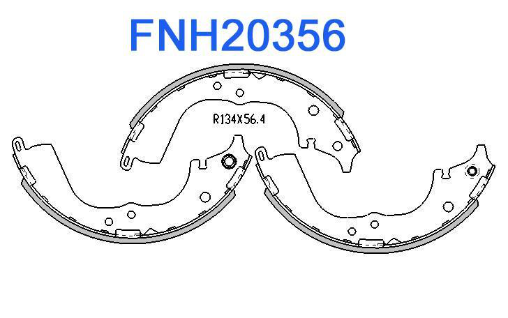
Reference No.
| FMSI No. | TRW No. | FERODO No. | WVA No. | OE No. |
| GS8693 | FSB563 | 04495-26180 04495-26190 04495-26210 04495-35200 J04 495 352 00 |
Car Application
| JINBEI (BRILLIANCE) | ||
| JINBEI (BRILLIANCE) (BRILLIANCE) GRANSE MPV 2.0 | MPV | 2007- |
| TOYOTA | ||
| TOYOTA HIACE III Box (YH7_, LH6_, LH7_, LH5_, YH5_, YH6_) 2.0 (RCH102_, RCH112_) | Box | 1990-1995 |
| TOYOTA HIACE III Box (YH7_, LH6_, LH7_, LH5_, YH5_, YH6_) 2.4 (RZH10) | Box | 1989-1995 |
| TOYOTA HIACE III Box (YH7_, LH6_, LH7_, LH5_, YH5_, YH6_) 2.4 D (LH10_, LH11_) | Box | 1989-1995 |
| TOYOTA HIACE III Box (YH7_, LH6_, LH7_, LH5_, YH5_, YH6_) 2.4 D (LN10, LH11) | Box | 1989-1995 |
| TOYOTA HIACE III Box (YH7_, LH6_, LH7_, LH5_, YH5_, YH6_) 2.8 D (LH11, LH10) | Box | 1989-2000 |
| TOYOTA HIACE III Box (YH7_, LH6_, LH7_, LH5_, YH5_, YH6_) 3.0 D (LH17_, LH16_) | Box | 1998-2004 |
| TOYOTA HIACE III Wagon (_H1_) 2.0 (RZH102) | Bus | 1989-1998 |
| TOYOTA HIACE III Wagon (_H1_) 2.4 (RZH103) | Bus | 1989-1995 |
| TOYOTA HIACE III Wagon (_H1_) 2.4 (RZH12_) | Bus | 1996-2004 |
| TOYOTA HIACE III Wagon (_H1_) 2.4 D (LH102) | Bus | 1989-1995 |
| TOYOTA HIACE III Wagon (_H1_) 2.4 D (LH5_, LH6_, LH7_, LH10_, LH11_) | Bus | 1987-2004 |
| TOYOTA HIACE III Wagon (_H1_) 2.5 D-4D 4WD | Bus | 2001-2004 |
| TOYOTA HIACE III Wagon (_H1_) 2.8 D (LH12_) | Bus | 1989-2000 |
| TOYOTA HIACE III Wagon (_H1_) 3.0 D (LH18_) | Bus | 1998-2004 |
| TOYOTA HIACE IV Box (LXH1_, RZH1_, LH1_) 2.4 (RCH12_, RCH22_) | Box | 1995-2005 |
| TOYOTA HIACE IV Box (LXH1_, RZH1_, LH1_) 2.4 4WD (RCH18_, RCH28_) | Box | 1995-1998 |
| TOYOTA HIACE IV Box (LXH1_, RZH1_, LH1_) 2.4 D (LXH12_, LXH22_) | Box | 1995-2006 |
| TOYOTA HIACE IV Box (LXH1_, RZH1_, LH1_) 2.4 D (LXH12_, LXH22_) | Box | 1995-2001 |
| TOYOTA HIACE IV Box (LXH1_, RZH1_, LH1_) 2.4 TD (LXH12_, LXH22_) | Box | 1995-2006 |
| TOYOTA HIACE IV Box (LXH1_, RZH1_, LH1_) 2.4 TD 4WD (LXH18_, LXH28_) | Box | 1995-2006 |
| TOYOTA HIACE IV Box (LXH1_, RZH1_, LH1_) 2.4 i (RZH10) | Box | 1995-2005 |
| TOYOTA HIACE IV Box (LXH1_, RZH1_, LH1_) 2.5 D-4D (KLH12_, KLH22_) | Box | 2001-2006 |
| TOYOTA HIACE IV Box (LXH1_, RZH1_, LH1_) 2.5 D-4D (KLH12_, KLH22_) | Box | 2001-2006 |
| TOYOTA HIACE IV Box (LXH1_, RZH1_, LH1_) 2.5 D-4D (KLH12_, KLH22_) | Box | 2006- |
| TOYOTA HIACE IV Box (LXH1_, RZH1_, LH1_) 2.5 D-4D (KLH12_, KLH22_) | Box | 2006- |
| TOYOTA HIACE IV Box (LXH1_, RZH1_, LH1_) 2.5 D-4D 4WD (KLH12_, KLH22_) | Box | 2001-2006 |
| TOYOTA HIACE IV Box (LXH1_, RZH1_, LH1_) 2.5 D-4D 4WD (KLH18, KLH28_) | Box | 2001-2006 |
| TOYOTA HIACE IV Box (LXH1_, RZH1_, LH1_) 2.5 D-4D 4WD (KLH28_) | Box | 2006- |
| TOYOTA HIACE IV Box (LXH1_, RZH1_, LH1_) 2.7 (RCH13_, RCH23_) | Box | 1998-2006 |
| TOYOTA HIACE IV Box (LXH1_, RZH1_, LH1_) 2.7 4WD (RCH19_, RCH29_) | Box | 1998- |
| TOYOTA HIACE IV Bus (_H1_, _H2_) 2.4 (RCH12_, RCH22_) | Bus | 1995-1998 |
| TOYOTA HIACE IV Bus (_H1_, _H2_) 2.4 4WD (RCH18_) | Bus | 1995-1998 |
| TOYOTA HIACE IV Bus (_H1_, _H2_) 2.4 D (LH10_, LH11_, LXH12_) | Bus | 1999-2006 |
| TOYOTA HIACE IV Bus (_H1_, _H2_) 2.4 D (LH10_, LH11_, LXH12_, LXH22_) | Bus | 1995-2006 |
| TOYOTA HIACE IV Bus (_H1_, _H2_) 2.4 TD (LXH12_, LXH22_) | Bus | 1995-2006 |
| TOYOTA HIACE IV Bus (_H1_, _H2_) 2.4 TD 4WD (H18/28) | Bus | 1995-2006 |
| TOYOTA HIACE IV Bus (_H1_, _H2_) 2.5 D-4D (KLH12_) | Bus | 2001-2006 |
| TOYOTA HIACE IV Bus (_H1_, _H2_) 2.5 D-4D (KLH12_, KLH22_) | Bus | 2001-2006 |
| TOYOTA HIACE IV Bus (_H1_, _H2_) 2.5 D-4D (KLH12_, KLH22_) | Bus | 2001- |
| TOYOTA HIACE IV Bus (_H1_, _H2_) 2.5 D-4D (KLH12_, KLH22_) | Bus | 2006- |
| TOYOTA HIACE IV Bus (_H1_, _H2_) 2.5 D-4D 4WD (KLH12_, KLH18_, KLH22_, KDH20_, KDH21_,… | Bus | 2005- |
| TOYOTA HIACE IV Bus (_H1_, _H2_) 2.5 D-4D 4WD (KLH12_, KLH22_) | Bus | 2001-2006 |
| TOYOTA HIACE IV Bus (_H1_, _H2_) 2.7 (RCH13_, RCH23_) | Bus | 1998-2001 |
| TOYOTA HIACE IV Bus (_H1_, _H2_) 2.7 (RCH13_, RCH23_) | Bus | 2001-2006 |
| TOYOTA HIACE IV Bus (_H1_, _H2_) 2.7 4WD (RCH13_, RCH19_, RCH23_) | Bus | 1999- |
| TOYOTA HIACE IV Bus (_H1_, _H2_) 2.7 4WD (RCH19_) | Bus | 1998-2006 |
| TOYOTA HIACE V Box (TRH2_, KDH2_) 2.5 D-4D | Box | 2006- |
| TOYOTA HIACE V Box (TRH2_, KDH2_) 2.5 D-4D (KDH200, KDH220) | Box | 2006- |
| TOYOTA HIACE V Box (TRH2_, KDH2_) 2.5 D-4D (KDH200_, KDH202_, KDH212_, KDH222_) | Box | 2006- |
| TOYOTA HILUX V Pickup (_N_, KZN1_, VZN1_) 2.4 D | Pickup | 1995-1997 |
| TOYOTA HILUX V Pickup (_N_, KZN1_, VZN1_) 2.4 D (LN5_, LN8_, LN9_, LN14_, LN15_) | Pickup | 1992-1997 |
| TOYOTA HILUX VI Pickup (_N1_) 2.4 D (LN150, LN145) | Pickup | 1997-2006 |
| VW | ||
| VW TARO 2.4 D | Pickup | 1994-1997 |
| VW TARO 2.4 D | Pickup | 1989-1997 |
Technical data
| Position | Rear Axle |
| Diameter | 270 mm |
| Width | 58 mm |
MOQ: 50sets each items, 2000 sets for one order.
Package: Plastic bag + FRONTECH Color Box or Customer Brand Box +Pallet+Container
4 PCS=1 set
200 sets = 1 Pallet
5000sets= 1*20’GP
Related products:
Brake Pads
Brake Discs
Truck Brake Pads,
Brake Sensor
Pad Kits
Brake Drums
Samples policy: One or two sets with no charge
How to Replacement New Drum Brake Shoes?
Listen To What Our Clients Say About Our Brake Pad

Keep Updated On Latest Brake Pad Newsletter
How to Replacement New Drum Brake Shoes?
Step 1
Remove the Brake Drum: After the wheel has been removed use a small chisel with a hammer to remove the bearing dust cap. On some cars the drum will just slide off or be held on by thin sheet metal clips which will need to be removed prior. If the drum is stuck continue down this guide for removal instructions.
Remove the bearing dust cap and the axle bearing retainer nut will be exposed.
Choose the correct size socket usually 22mm to 24mm and remove the axle bearing retainer nut. This can be done using a breaker bar.
Gasp the drum and with a twisting and pulling motion remove it from the car. Turning the drum helps release the unit from the axle and the brake shoes.
On a non bearing style of brakes there will be two methods to remove the drum. Normally a brake drum will just lift off of the axle flange but rust can sometimes make the drum stuck. To remove a stuck drum use WD40 and spray it between the axle flange, lugs studs and the drum and let it sit for about 15 minutes.
The first way to remove the brake drum is too insert two bolts which are usually 8mm x1.25 and then tighten them equally which will push the drum outward for removal.
The second way is to be used if no bolt holes are available, or if you don’t have the bolts. Use a hammer and strike the drum between the lug studs. This will “shock” the drum from the axle flange. Use caution when using the hammer so you do not hit the wheel studs. This is the best method of removing the stuck brake drum.
Step 2
Clean the Brakes: Hang a bucket on the axle which will be used for a catch basin. This step will keep the brake dust down to a minimum and make the job cleaner and more enjoyable.
Use regular water to rinse away harmful dust particles and allow drying. Wipe away any water from the axle. If you use a garden hose for this step be careful not to blow the brake dust in the air when the pressure from the hose hits the shoes. Use the fan feature of the nozzle which will help keep the brake dust down.
Step 3
Inspect the Brake Shoes: Inspect the brake shoe thickness to the new brake shoes. Each shoe can be little different and requires a comparison.
When the brake shoes become overheated it can crack the brake lining of the shoe which indicates a failure that requires replacement. When a brake shoe is in this condition large piece of the lining can come loose and lodge between the shoe and drum causing the wheel to lock up.
Step 4
Check the Wheel Cylinder: To check the wheel cylinder use a flat blade (standard) screwdriver and pull back the rubber cups to check for the presents of brake fluid which is an indication of failure. Some people like to replace the wheel cylinders every time a brake job is done which is the preference of person doing the job. If the car is fairly new you can leave them if they are not leaking. If many miles is on the car or the vehicle is used for extreme duty service you should replace them.
Step 5
Brake Shoe Removal: Begin the brake shoe removal by identifying the primary brake shoe spring or springs. (Note: Some brakes utilize two primary springs.) We feature two videos at the bottom of this article which shows different designs of brake shoes please watch them to get an idea of the different kinds available on cars, light trucks and SUV’s.
Use a pair of side cutters and grasp the spring and pull it towards the brake shoe until it is released. This can take some doing so hang in there.
Once the spring has been released the opposite side will be easily removed.
Use a pair of needle nose pliers to release the brake shoe hold down clips there will be one on each shoe. On some types of brakes you are want to use a brake tool for this.
After both shoe hold down or anchor clips have been released grasp both brake shoes firmly and pull slightly outward which will allow the shoes to separate from the backing plate and wheel cylinder.
Once the brakes shoes are free from the backing plate pull the parking brake cable spring downward and release the cable from the parking brake arm.
The brake shoe set will become free from the backing plate. Hold the shoe set together because it will want to come part.
Step 6
Replace the Wheel Cylinder: Like we motioned before the wheel cylinder must be a good condition or it will leak and ruin the new brake shoes. If the car is fairly new you can let it go until the next brake job, but if the wheel cylinder is old or leaking it must be replaced. If the wheel cylinder fails you will lose part of the braking system pressure and it may cause an accident. It is also advisable to replace the wheel cylinders as a set (both sides) if one is leaking the other side can’t be far behind.
Step 7
Install the New Brake Shoes: Use a medium size flat surface to initiate spring and e-bake lever swap onto the new shoes. Take note how how the springs and shoe are situated. Now would be a good time to snap another picture using your phone. At this point a brake new spring hardware kit (combo kit) can be used if the vehicles brakes have been overheated or the car has more than 80,000 miles on it. Springs can become brittle and lose their strength when they get hot and then cooled.
Once the new brake shoes have been NO boxed match the warn brake shoes to the new brake set. They should be identical in most cases. Sometimes the manufacturer will have an update that can make the shoe a little different but no very often.
Align the new brake shoes with the old set on a flat table or bench and start removing brake springs and swapping them to the new shoe set. Try not to get the linings of the new shoe set dirty as this can distort their braking ability. If dirt or grease does get on the linings try to use a small amount of brake cleaner to help remove it.
Also remove the parking brake lever and self adjuster from the old shoe set. If the self adjuster is the threaded type disassemble it can clean the threads while adding a small amount of brake lube to help it work more easily.
Reset the adjuster by pushing the adjuster wheel away from the pin and install it onto the new shoe along with the mounting spring, or wind the threads inward to make the adjuster as short as possible.
Once all necessary brake components have been swapped over the new shoe set is ready for installation.
Before installing the new brake shoes use a pair of side cutters (dikes) to grip the parking brake spring holding it in place away from the cable end. This will help attach the parking brake level with little effort.
Re-position the shoe set onto the backing plate and over the wheel cylinder while holding the shoes in place. This is where a mechanics can use three hands.
While holding the brake shoes in place position and install the brake shoe retainer clips.
Once the retainer clips have been installed re-position and attach the lower brake spring using a pair of side cutters (dikes)
To complete the new brake shoe set re-installation connect one side of the spring to the brake shoe. Attach it to the side that is easiest for you to get leverage on the opposing side.
Using a pair of side cutters grip the spring and pull in toward the secondary shoe while connecting it. This completes the shoe assembly phase of your repair.
All brake shoes require a self a adjuster of some kind which must be reset and then re-adjusted when replacing brake shoes and then be fine tuned once the drum is re-installed.
Step 8
Re-installing or Replacing the Brake Drum:Before the brake drum can be re-installed it must be replaced or re-machined to ensure a square surface for the new shoe to contact when braking. Here is an example of uneven wear (lip) which will affect the braking ability of the new brake shoes which are perfectly flat.
Re-install the re-machined or new brake drum. Installing and removing the drum while spinning it. Then move the shoe self adjuster outward slightly each time until you hear the shoe gently contact the drum. This process may need to be performed a number of times to fine tune the self adjuster. The drum should spin freely with slight contact with the brake shoes.
When replacing a brake drum match the new drum to the old one, they should be an identical match. All brake drums have a maximum diameter which is the limit of what it can be re-machined too. The more metal that is removed the less effective the drum will be in removing heat. This excess heat can cause brake fade and will make the drum warp and become out of round. This condition will cause the car to brake unevenly which is unsafe.
Use a clean shop towel and brake or carburetor cleaner to wipe out the shoe surface. It’s still a good idea to free the surface from dirt and grease.
Once the drum has been installed insert the drum-bearing retainer nut by hand to avoid cross threading. Some drum will just slide onto the axle with no nut required.
After threading the retainer nut onto the axle tighten it to manufacturer’s specifications usually between 170 and 240 foot pounds of torque. At this point the brake drum should still spin freely with minimal contact to the brake shoes. If the brake drum does not spin the shoes are too tight and the drum must be removed to readjust the shoes inward. Don’t think the shoes will just wear in. This is a mistake because the brake will heat up and expand which will make the problem even worse until the wheel stops rolling altogether.
Reinsert the bearing dust cap by gently tapping it into place using a hammer. These caps are made of thin sheet metal and can bend and distort if hammered on to hard in which case they will lose their ability to hold onto the drum and must be replaced. Once competed on the both sides follow the guide on how to re-install the wheel and remove the car from the jack stands.
Step 9
Check the Brake Fluid: Lift the hood of the car and locate the brake master cylinder’s fluid reservoir. Clean the top of the brake master cylinder using a shop towel then loosen and remove the lid.
If the fluid level is low add brake fluid from a sealed container until the level reaches the fill line. The fluid level may or may not be low.
Re-install and tighten the reservoir cap.
Step 10
Set the Rear Brake Shoes: Once both wheels have been completed and the car is back on the ground the brake shoes are ready to be set to the drum. Use your foot and hold the brake pedal down.
Activate the parking brake lever several times. This operation will give the brake shoes a final adjustment automatically by using the self adjuster. This will also help the brake pedal’s position (increased firmness).
Each brake shoe replacement varies and some applications require a spring removal tool. Drum style brakes are more susceptible to moisture (water) which can decrease braking ability.
When replacing brake shoes check spring hardware (return and mounting) and replace if damaged or broken. On larger vehicles replacing the spring hardware is necessary every time the brakes are replaced. Some brake systems must be adjusted after assembly. These systems generally provide an adjustment slot which is used to manually turn an adjuster wheel to obtain proper shoe to drum clearance. It is a good idea to bleed the brake system the job is completed is case air has entered the system during the job.